
How to Calculate DH Parameters for Robotic Arms: A Beginner's Guide
- Karan Bhakuni
- Jan 11
- 6 min read
Updated: Jan 12
Understanding DH Parameters: A Simple Hack for a Complex Problem
We know that in the world of robotics, each link of a robot has 6 degrees of freedom: the position (x, y, z) and the orientation (roll, pitch, yaw) about some global axis. But, hold on a second! As we start adding more and more links, the number of variables skyrockets, making the problem a lot more complicated. And honestly, who wants to deal with that?
This is where the geniuses, Jacques Denavit and Richard Hartenberg, come in. They thought, "What if we could simplify this?" And guess what? They found a way! Instead of needing 6 parameters to define each link, they came up with just 4. Yes, you heard that right – 4 parameters that can define any link in a robot, making all those complex calculations a breeze. Now that’s what I call innovation! But there is a hack that it has to be a serialized chain manipulator with each joint having only 1 DOF.
The 4 Key Parameters That Unlock Motion
To understand the DH convention, we need to grasp four main parameters for each joint:
θ (Theta): The joint angle, a measure of how much the joint is rotated about its axis.
d: The offset along the previous z-axis, shifting the link along the z-axis.
a: The link length, the distance between two consecutive joints along the x-axis.
α (Alpha): The link twist, the angle between the z-axes of two consecutive joints.
Sounds like textbook jargon, right? You’ll find these definitions in any robotics book. But here’s the twist—I’m here to make this easy and relatable for you!
We’ll use our robot model as a reference. If you haven’t checked out my URDF blog yet, go ahead and give it a read. It’s packed with details about the robot we’re working with, and we’ll use that as our guide to finding the DH parameters.
To keep things simple, let’s divide this process into two parts:
Assigning DH axes.
Calculating DH parameters for each joint.
Ready to Dive In? Let’s Have Some Fun!
A) Assigning DH Frames
In Fig 1, we have actual frames defined for our robot. Let’s use them to understand and calculate the DH parameters step by step.

In Fig 1 you can see thatyou’ll notice that I’ve already assigned the z-axis for my 6R robot. These aren’t just arbitrary lines, they represent the actual axes of rotation for each joint. Its means the joints are rotating actually about these axis only. We will keep the direction of z axis same so that DH axis of rotation and actual axes of rotation will be same. Keeping the z-axes consistent makes the process intuitive and ensures our DH parameters accurately represent the robot's real movements.
Note: While assigning DH paramaters always keep in mind that your frame assignments always takes all the paramters of robot in picture like link lengths and offsets.
To start with DH parameters, first assign z axis to all the joints in the same way how they actually are.
Now we will assign x axis to our frames. Let me give you some bookish rules to assign these x axis then we will move how i have assigned them in my robot.
Z axis: zi-1 to zi along joint axis
X axis: xi-1 along common normal between zi-1 to zi
Origin of each joint: Oi-1 at the intersection of zi-1 and xi-1
Y axis: yi-1 and yi using right hand frame
Similarly xi and Oi can be defined.
Now lets do it for our robot.
x0 is perpendicular to both z0 and z1. And the intersection fo x0 and z0 is the origin of that joint that is 0 in this case. |  |
x1 is perpendicular to z1 and z2 while origin1 is the intersection of z1 and x1. |  |
x2 is perpendicular to z2 and z3 while origin2 is the intersection of z2 and x2. |  |
x3 is perpendicular to z3 and z4 while origin3 is the intersection of z3 and x3. |  |
x4 is perpendicular to z4 and z5 while origin4 is the intersection of z4 and x4. |  |
x5 is perpendicular to z5 and z6 while origin5 is the intersection of z5 and x5. |  |
x6 is perpendicular to z6 and ze while origin6 is the intersection of z1 and x1. While xe is perpendicular to z6 and ze and e is at intersection of ze and xe. | 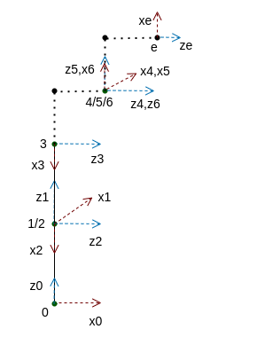 |
Curious about some questions on Frame Assignment? Let me try to Answer them....
Now you might be having some doubts about the frames, let me just take you through all the questions coming to your mind.
1. Why 4,5,6 origins are at same location?
Its because of the fact that we have followed modified DH parameter rules and one of the biggest reason of having all those points together at one point(called as wrist) is to solve the kinematics of robot. In further blogs (Stay Tuned) we will also solve forward and inverse kinematics of robot and, While solving inverse kinematics this will be one of the game changers.
2. How i have defined the x-axis of end effector as there is no z-axis after it?
The convention we follow is that the x-axis of the end effector should align with the x-axis of the last frame, which is Frame 6 in our case.
3. Where is the y axis of each joint? Why we have not assigned y axis is it not required?
Actually we don't require y axis while finding DH Parameters. But still if you want to add y-axis its very easy just use right hand curl rule to do that. Try it out! If you're able to do this, drop a comment below, and I'll help
you! 😊"
B) Now we are done with DH Frames.. Lets find Modified DH parameters
First understand the rules and then we will find it:
αi-1 (Link twist) : angle from zi-1 to zi about xi-1
ai-1 (link length): distance from zi-1 to zi along xi-1
di (Link offset) : distance from xi-1 to xi along zi
θi (joint angle): angle from xi-1 to xi about zi
Using the above rules the DH table is created:
For Joint 1
α0 = angle form z0 to z1 about x0 = 0
a0 = distance from z0 to z1 along x0 = 0
d1 = distance between x0 and x1 along z1 = l1
θ1 = angle from x0 to x1 about z1 = θ1+π/2 [Here π/2 is always the angle and θ1 will be dependent on user]
For Joint 2
α1 = angle form z1 to z2 about x1 = π/2
a1 = distance from z1 to z2 along x1 = 0
d2 = distance between x1 and x2 along z2 = 0
θ2 = angle from x1 to x2 about z2 = θ1-π/2 [Here π/2 is always the angle and θ2 will be dependent on user]
Try it for other joints by yourself.......
Feel free to comment in case of any doubt
Lets answer some of the questions coming to your mind.....
From where we get these values of lengths ?
See fig(1) and you can easily see the lengths. Still i m adding one more Fig2 for your refenrece showing side by side actual axes and Modified DH parameters axes.

Fig 2: Actual Joints(left) and Modified DH Frames(right) of 6-axis Manipulator Where is the end effector parameters in the table? Don't we require it for calculations?
While these parameters are definitely crucial for our calculations, it's generally not recommended to include them in the DH table. The reason? The end effector can change at any time, so its parameters might not stay fixed. However, the frames up to Joint 6 remain constant, regardless of the position or orientation of the end effector.
That being said, I’m still adding these parameters separately to keep everything clear and organized.
Wrapping It Up: Modified DH Parameters
And there we have it! By now, you should feel confident enough to tackle the Modified DH parameters for any robot with rotary joints, where each link brings 1 degree of freedom to the table. It's like cracking a puzzle, right?
But wait... what's next?
Next, we dive into the Kinematics of Robots—starting with the ever-so-cool Forward Kinematics (FK) and then venturing into the enigmatic world of Inverse Kinematics (IK). Things are about to get even more exciting, so stay tuned!
As we all are learning from each other feel free to give your feedback as comments. All the improvements will be highly entertained.....
Because I Don’t Know Everything: My Go-To Resources
Robotics and Control by RK Mittal and IJ Nagrath
Comentarios